Driver Offset CalculatorIntroductionWith this "audiofile" I will be discussing how to determine the driver offset which is used in a crossover simulator. I will show how to calculate how much extra offset is required based on the driver's location on the baffle. These calculations will assume an estimate of the base acoustic center offset of the driver. These calculated values can be used for processed manufacturer's data or measured data with a minimum phase response. They can then be used in a crossover simulator like Speaker Workshop or the Passive Crossover Designer. The calculations can also be used to translate a measurement distance to a different listening distance when simulating the crossover.Calculating Offset for Minimum Phase DataI will first discuss how to determine the acoustic offset for a driver that has minimum phase characteristics (the phase was generated by performing a Hilbert transform on the SPL data). First you will need to know the base acoustic offset of each driver except for the tweeter. It is usually pretty close to the distance from the flange to the point where the voice coil connects to the cone (or near the spider). I usually use estimates that work fairly well (4" driver=0.5"AC, 5" driver=0.6"AC, 6" driver=0.75"AC, 7" driver=1"AC, 8" driver=1.5"AC, 10" driver=2"AC). Once this value is known for every driver you have to determine how much farther away each driver is from the listening position relative to the distance to the tweeter.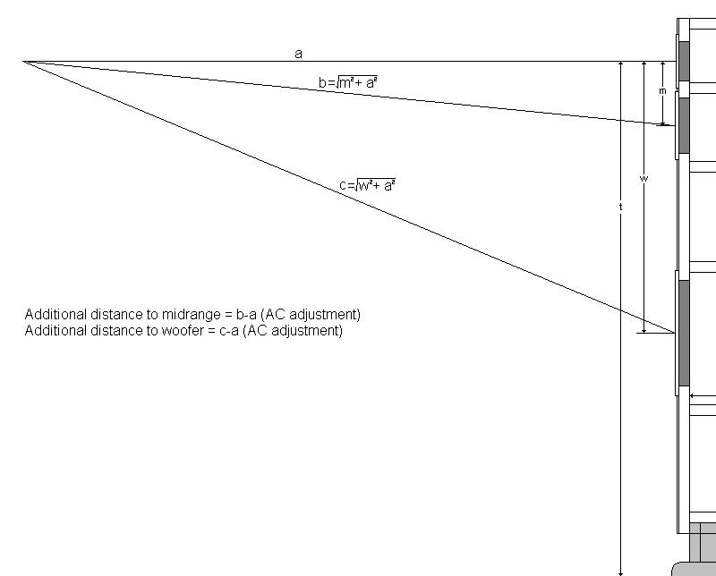 Above is a diagram of a three way speaker and a calculator that determines the additional amount of driver offset that you have to use based on the given measurement/listening distance. Consider the example of a measurement distance of 36", a tweeter to midrange distance of 5" and a tweeter to woofer distance of 20". For this example we will assume a 5" driver for the midrange and an 8" driver for the bass. The calculator reveals values of 0.346" and 5.183". Assuming that the midrange base acoustic center is recessed by 0.5" the driver offset that should be used in the crossover simulator for the midrange should be 0.846" (0.5+0.346). In Speaker Workshop you would enter -0.846" for the midrange offset value (some other simulators use the opposite sign convention including the Passive Crossover Designer). For the woofer you would use -6.683" (1.5+5.183) for the woofer driver offset in SW. The calculator above will work with any dimensions, just keep in mind that all units must be the same for every value (including the calculated values). Calculating Offset for Translating Measurements to a Different Listening DistanceI will address another situation. Say you measured a speaker with the microphone at the tweeter height and a distance of 36". If you wanted to see the performance as if you were listening or measuring from a further distance you can adjust the acoustic center values in the crossover simulator to reflect this extra distance. To do this first calculate the values for the midrange offset adjustment and the woofer offset adjustment. In our example above these values are 0.346" and 5.183". Then recalculate those values for a different measurement/listening distance. Lets assume 10' (120") for this example. We now get values 0.104" and 1.655". I will assume the sign convention that Speaker Workshop uses in what follows (a negative offset represents moving the acoustic center behind the baffle). In order for our crossover simulation to represent the conditions of 10' away based on measurements made at 3' away we have to take each offset adjustment value and subtract them. For the midrange we get 0.346-0.104=0.202" and this is the value that should be used in Speaker Workshop for the midrange driver offset. This indicates that the midrange is actually closer to the listening position _relative_ to the tweeter based on the new listening position. For the woofer the value is 3.528". This method can be handy if you don't have a lot of room to measure and need to measure at a distance shorter than your typical listening distance.ConclusionSo this is a pretty simple way of determining how to estimate the driver offset of drivers in a crossover simulation for a multiway speaker. When working with manufacturer's data processed with the FRD consortium tools you will need to perform this analysis prior to simulating the crossover. This calculator can also be used to translate measurements taken at one distance to a listening scenario at a different distance. If you expanded the trigonometry a bit you can calculate the driver offset adjustements for measurements taken at different listening heights. Just be careful because none of this analysis takes into account the off axis performance of drivers so some scenarios may not be accurate at representing the true performance of the speaker at that distance if the actual driver's response begins to roll off due to off axis dispersion issues. |