Locating the tweeter to reduce diffraction effects


Introduction

In this section I will discuss how locating the tweeter on the baffle affects the tweeter's response and the best way to place the tweeter to minimize these diffraction effects. This analysis will assume that a standard 1" dome tweeter is mounted on a 9" wide rectangular baffle which is an average width for most two-way speaker designs. The theories in this analysis are applicable to any reasonable baffle width and configuration. It is also assumed for this analysis that the edges of the baffle are NOT rounded over thus representing the worst case baffle diffraction situation.

To understand the baffle diffraction plots presented in this section I'll give a quick overview of concept of baffle diffraction and baffle step. Lets assume a baseline condition of a tweeter operating with no baffle at all, not even any flange, just the dome. This characterizes the tweeter as operating in 4pi space or free field. In this scenario the output of the tweeter is allowed to radiate in all directions. Now when a baffle is added to the equation the tweeter is considered to be operating in 2pi space assuming that the baffle is infinitely wide and tall. The output of the tweeter operating in 2pi space will be 6dB greater than that of it operating in 4pi space. This is due to the fact that any soundwaves that would normally travel behind the tweeter are being reflected forward and effectively double the output of the tweeter as a result. When the baffle is of finite size, the distance between the tweeter and the edge of the baffle determines what frequency the tweeter's soundwaves transition from 2pi to 4pi space. In other words, if the wavelength of the tweeter's output is shorter than this distance then those wavelengths are operating in 2pi space. This is because they are short enough to be reflected off of the baffle and thus those frequencies experience a 6dB gain due to the baffle. If the wavelength of the tweeter's output is greater than the distance between the tweeter and the edge of the baffle then those wavelengths (or corresponding frequencies) are operating in 4pi space. These frequencies do not experience a 6dB gain because the soundwaves are effectively "wrapping" around the baffle instead of reflecting forward. In the transition between 2pi and 4pi space near the baffle edge (and corresponding wavelength) a phenomenon known as baffle diffraction occurs. I won't go into the detail of baffle diffraction but there are resources on the net that discuss this topic. Essentially, baffle diffraction causes peaks and dips in the response in the frequency region near the 2pi to 4pi space transition. The plots that I will present below represent how much the tweeter's response will be altered due to baffle diffraction effects relative to a tweeter operating in free-space (otherwise known as 4pi space).

Worst case scenario - equidistant
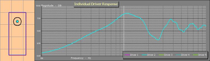
First I will discuss the worst case scenario when it comes to location of a tweeter on the front baffle. In this situation the tweeter is located exactly 4.5" from the top, left side and right side. Thus it is equidistant from three of the sides of the cabinet. Above is a plot of the baffle diffraction effects. It reveals that this tweeter location causes a +/-2.5 dB ripple in the tweeter's response due to baffle diffraction. The reason the baffle diffraction effects are so severe is due to the fact that the tweeter is located 4.5" from three of the four sides of the cabinet. Thus the wavelength at which the transition between 2pi and 4pi space is identical in three directions and the baffle diffraction effects are essentially being multiplied by 3 at those frequencies. This represents the worst case scenario when using a rectangular baffle, however, a circular baffle with the tweeter located dead center is much worse than this because the distance between the tweeter and the edge of the baffle is the same in every direction and the baffle diffraction effects are really amplified.

Tweeter shifted up

In the next case the tweeter is shifted upwards so that the distance between the tweeter and the top of the cabinet is less than the distance between the tweeter and the other two adjacent sides. The center of the tweeter in this case is 3" from the top of the cabinet. As you can see in the plot above, the diffraction effects aren't as severe as the previous case and there is a +/-1.5 dB ripple in the tweeter's response. The response improved because some of the diffraction effects associated with the distance between the tweeter and the top of the cabinet have been moved up in frequency due to the shorter distance (or corresponding wavelength). Now when positioning the tweeter it is a good idea to make sure that these distances between the tweeter and each side are not multiples of each other. In other words the baffle diffraction effects would look a little worse if I placed the tweeter 2.25" from the top because it is half of the 4.5" distance between the tweeter and the side.

Best case scenario - Golden Ratio
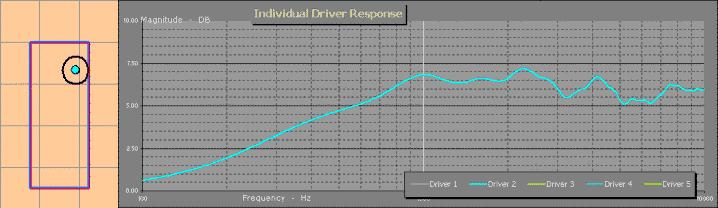
In this final case I've located the tweeter in a way that the distances between the center of the tweeter and each side is different. Furthermore I chose these distances according to the Golden Ratio. You might have heard of the Golden Ratio when working with enclosure dimensions. It is recommended to build a cabinet with dimensions according to the Golden Ratio of approximately 1.0/1.6/2.6 in order to reduce the effects of standing waves within the cabinet. The Golden Ratio is chosen because it spaces out the wavelengths in such a way that there is minimal combination between them due to harmonics. If you look at multiples of each number in the Golden Ratio there are few, if any, that coincide with each other. If I'm doing a poor job of explaining this and you're confused just know that is a good ratio that works well for enclosure dimensions and locating a driver on a baffle. With the Golden Ratio applied I ended up with the tweeter being located 6.5" from the left, 4" from the top and 2.5" from the right. As you can see from the plot above this tweeter location results in the flattest response of them all and shows a ripple of about +/-1 dB which is pretty darn good. This is just about as good as you can do on a flat rectangular baffle with no edge rounding. If your cabinet dimensions don't allow you to do this or you don't want to offset the tweeter this far just make sure you avoid distances that are multiples of each other and you'll be fine.

Conclusion

In this discussion I demonstrated how critical the location of the tweeter on the speaker baffle is with regards to baffle diffraction effects. The key to reducing these baffle diffraction effects is to place the tweeter at different distances from each side and to avoid distances which are multiples of each other. These baffle diffraction effects are based on an on-axis listening position. Off-axis these baffle diffraction effects are reduced and it is a good idea to design the crossover with the off-axis response in mind as well but that's another topic for another day.